Impedance matching with a cable of same impedance?
Recently in the german magazine "Funkamateur", there were two articles where the author claimed that it is possible to get a better standing wave ratio (VSWR) by using a specific lengths of 50Ω cable.
The first article was about a duo-band antenna for the 70cm and 2m ham radio bands [1]. This casually mentioned that the VSWR could be improved by using a specific length of 50Ω cable and provided a link to a software by the author to compute that length (in fact it was claimed that there are different lengths of cable that would achieve that purpose). It was claimed that this length of cable can transform the impedance (the word used was "Leitungstransformation").
In a second article -- prompted by several readers who wrote letters to the editor -- the author provided measurements that clearly showed that, indeed, the VSWR was improved with a certain length of cable [2].
Now transmission line theory says that a transformation can only be achieved by a piece of line with a different impedance that the characteristic impedance of the system, see my recent article on the subject. So there must be another reason why the impedance is changed – as clearly shown by the authors measurements. The author of the article claimed here that there is a discrepance between theory and practice – I'll show in the following that there is a reasonable explanation for the findings without dumping the existing electromagnetics theory.
The hint here is that the author did not use a balun or any other means that prevents current on the outer sheath of the feedline. So I had some fun modelling the setup with the antenna simulation program NEC2. The results should be reproduceable with any other antenna simulation program, at least if it contains a NEC core (e.g. EZNEC) which can model ground and not just free space. I've modelled the (simple two-element) antenna from the original article.
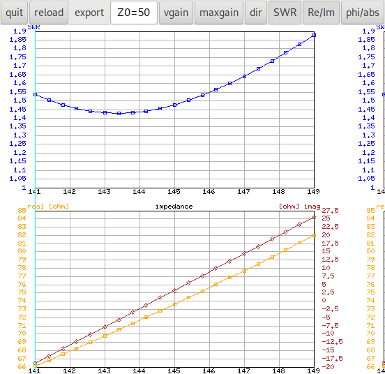
The following image shows the standing wave ratio (VSWR) and the impedance split into real and imaginary part directly at the antenna. The first NEC input file can be used to reproduce the results. Note that I'm using a Sommerfeld/Norton ground model with a medium quality ground. The antenna is located 15m above ground in the model because the antenna is meant to be used on a balcony.
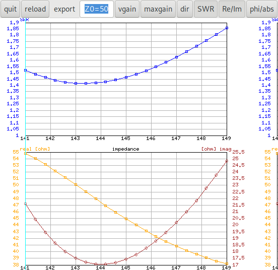
The next image shows the same antenna with a length of feedline (the length is the one for which the author claims that it can improve the VSWR). Note that the feedline is not modelled as a piece of wire but as a transmission line (which NEC provides as an abstraction). Again we show real and imaginary part. The electrical length (NEC uses only the electrical length when modeling transmission lines, no velocity factor is necessary) is about 1.81m computed by the formula in [1] with a velocity-factor of 1. It can be clearly seen that the impedance changes but the VSWR stays the same. The corresponding second NEC input file can be used to reproduce these results.
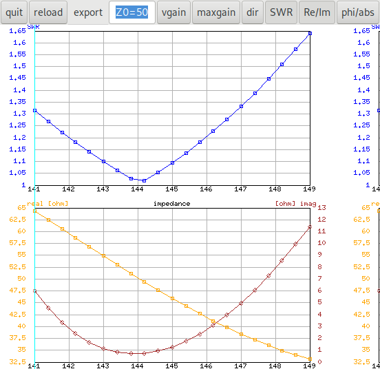
Now to simulate the conditions at the feedpoint when there is no balun I've modeled a wire between the antenna and the feedpoint at the end of the cable in the third NEC input file. The following image shows the model, we have an additional wire which represents the outside of the coax feedline. It is connected to the antenna at one point and to the end of the coax at the second point. The length of the cable is the physical length. Except for a small increase of the electrical length due to the isolation (not with the usual coax velocity factor, we're simulating only the outer braid!) the cable in the model needs to use the real physical lenght. We're using 1.484m from [1], table 3 for an Aircell5 with the factor n=1 in the table. Now we see that, indeed, as observed in the second article [2], the standing wave ratio VSWR is indeed smaller. The reason is, that due to a missing balun, the antenna itself has changed: The outer braid of the feedline is part of the antenna.
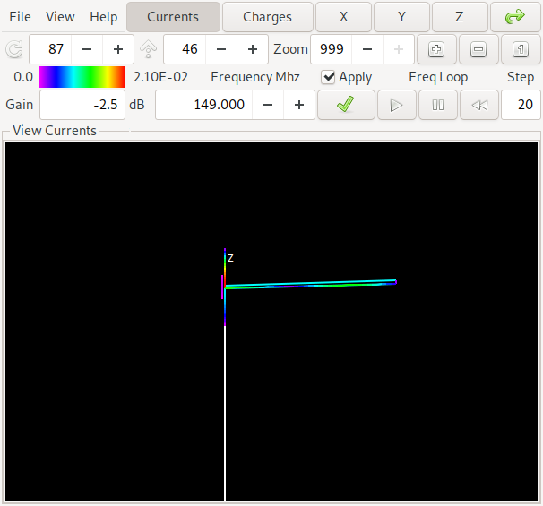
A view with the Linux program xnec2c shows the currents in the antenna and on the outer braid of the feedline. We can clearly see that there is current on the outer braid of the feedline.
So the electromagnetics theory is saved, there is a physical explanation of the phenomenon. It would still be interesting to model different influences like height above ground or different ground characteristics – and find out if the results above are reproduceable with different parameters since the author claims that the observed behaviour is well known ([2] p. 35).
| [1] | (1, 2, 3) Klaus Warsow. Duoband-Fensterantenne für das 2-m- und 70-cm-Band. Funkamateur, (9):712–714, September 2021. |
| [2] | (1, 2, 3) Klaus Warsow. Impendanzanpassung mithilfe von Koaxialkabeln. Funkamateur, (1):35–37, January 2022. |