Second SPI chipselect for Orange-Pi Zero
I recently tried to get a TPM-Module from Infineon made for the Raspberry-Pi working on the Orange-Pi Zero. The Chipselect of the TPM module is hard-wired to chipselect 1 (via a 0 Ω resistor that could be soldered to another location to use chipselect 0, the board has the necessary unpopulated solder pads).
The Orange-Pi uses the same connector as the Raspberry-Pi but uses SPI-1 (instead of SPI-0 on the Raspi) on connectors 19 (MOSI), 21 (MISO), 23 (CLK), and 24 (CS-0, the hardware-supported chipselect). Chipselect CS-1, which is a native chipselect on the Raspi, is a normal GPIO (PA10) on the Orange-Pi Zero. The SPI-Driver for the H2 Allwinner processor in the Linux kernel is supposed to support normal GPIOs as additional chipselects. But this didn't work in my case.
So I first tried to find out if something with my Device-Tree configuration was wrong or if I needed a patch to fix the SPI initialization. This search is documented in a discussion thread in the Armbian Forum. It turned out that my Device-Tree configuration was OK, the following is the Device-Tree Overlay I'm currently using for enabling GPIO PA10 on the Orange-Pi Zero as the second chipselect CS1:
// Enable CS1 on SPI1 for the orange pi zero
/dts-v1/;
/plugin/;

/ {
    fragment@0 {
        target = <&pio>;
        __overlay__ {
            spi1_cs1: spi1_cs1 {
                pins = "PA10";
                function = "gpio_out";
                output-high;
            };
        };
    };

    fragment@1 {
        target = <&spi1>;
        __overlay__ {
            status = "okay";
            pinctrl-names = "default", "default";
            pinctrl-1 = <&spi1_cs1>;
            /* PA10 GPIO_ACTIVE_HIGH (last 0) */
            cs-gpios = <0>, <&pio 0 10 0>;
        };
    };
};
But the Clock-Line of the SPI-Bus is set to high before the SPI bus transfer starts. This is shown in the following oszilloscope screen-dump for the builtin chipselect CS0:
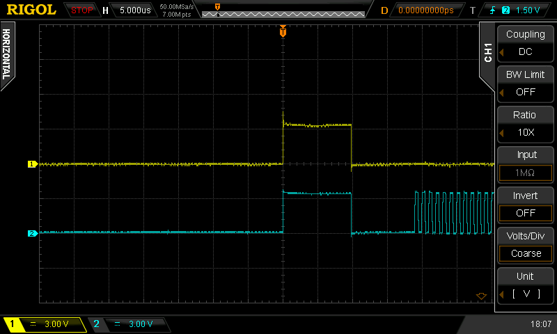
The clock line (blue) goes high before the transfer and then to low when the chipselect (yellow) goes low (chipselect is active low, the data on MISO/MOSI, not shown in oscilloscope picture, is sampled when the clock-line goes high). This may confuse some devices but works in most cases.
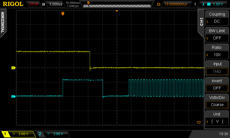
Now the picture looks different when we use the second chipselect CS1. In that case clock (blue) also goes high before the transfer but it does not go low when the chipselect (yellow) becomes active (low). This is a problem because a high clock line tells the SPI slave to sample the bus at that point. So all bits are right-shifted by one bit and the SPI slave only receives garbage.
When I had seen this, I remembered a patch I had seen at the end of the SUNXI project spidev page which fixes the problem of the clock line going high before the transfer (See the end of that page under the title "HIGH on SCK line right before transfer"). So I applied the patch.
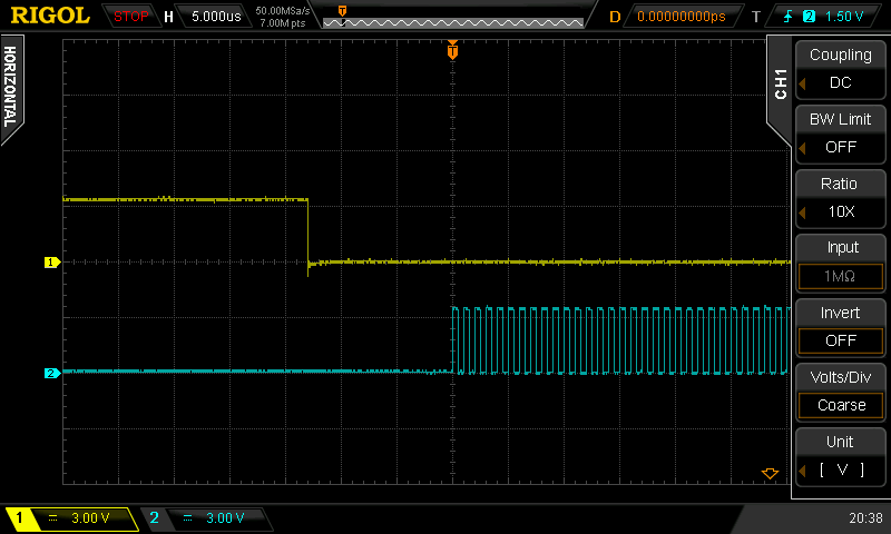
Looking at the next screen-dump from the oscilloscope, this shows again CS1 in yellow and clock in blue, you see that now the chip-select does not go high before the transfer starts. I haven't made a picture of this with CS0 (default chipselect) because the CS0 stays low all the time: It is low before the SPI is initialized and then stays low when the transfer starts. It doesn't show the bump in the clock line as in the very first picture before the patch.
I intend to convince the original author of this patch on the SUNXI project spidev page to submit this patch to the linux kernel because without it a second chip-select won't work. Failing that (so far I don't have an answer) I'll try myself to get the patch accepted.