Modding a PC Power Supply
WARNING: In the following I'm going to describe how to modify a power supply. Power supplies contain high voltages – even after removing the power plug they can still have high charges in capacitors. In some countries devices with mains power may be modified only by or under supervision of certified persons. So you should know what you're doing and be authorized to modify a power supply.
PC power supplies are cheap and readily available but the tend to produce the correct voltages only when the drawn current from all different voltages are within the minimum/maximum specs of the power supply. Drawing high current (but within the specs of the power supply) only from a single voltage lets this voltage drop below specification.
One example is the heat-bed of my 3D-printer: It used to have a PC power supply for the heat bed. The heat bed draws about 12A but only from the 12V line. The result was a voltage of about 10V when the heat-bed was heating.
Another use-case is the supply of several ARM based single-board computers (e.g. Raspberry-Pi or Orange-Pi) from a single 5V line. When using a PC-Power supply for this (without drawing current from the 12V lines) the nominal 5V voltage may drop below a value where the single-board computer works reliably.
A third example is the use of a power supply for powering the radio of a ham-radio operator: These radios typically don't output full power when powered with 12V or less, they typically need 13.6-13.8V for full power operation.
In all these cases a modification of the power supply that keeps the chosen voltage stable or even allows to modify the chosen voltage slightly (from 12V to 13.8V for hamradio operation) would be nice. How can we achieve that?
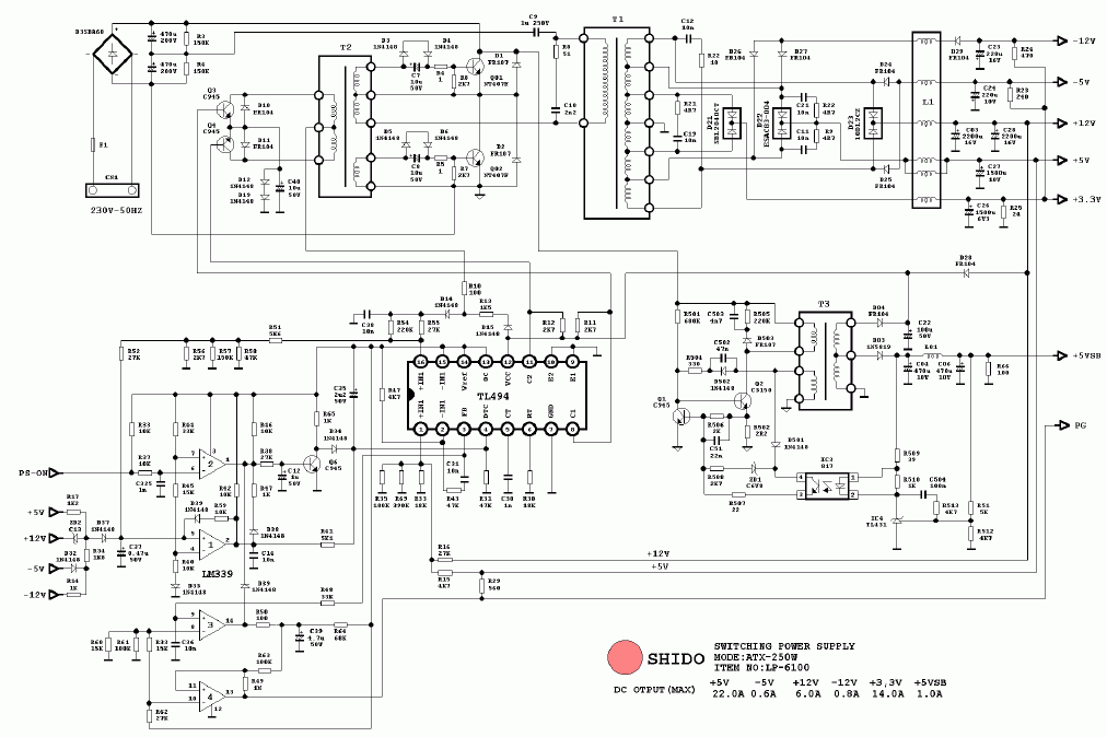
Many PC power supplies are based on the power regulator integrated circuits TL494 or KA7500 (they are pin-compatible). If you have one of those they can usually be modified for the purposes outlined above.
One schematic details of those supplies is a feedback-circuit that feeds back the 5V and the 12V voltage to the regulator IC. You can find a lot of power supply schematics on Dan's PC power supply page. Take the second of the TL494 or KA7500 based supplies, it has several resistors in parallel from pin 1 of the TL494 to ground, a 27kΩ-resistor from 12V to pin 1 and a 4.7kΩ-resistor from 5V to the same pin.
We can modify the voltage regulation by changing the feedback pins. Note that every power supply usually has different resistors to ground and different feedback resistors from 5V and 12V. As an example we replace the two feedback resistors to make the power supply provide stable 5V without caring for the 12V supply.
WARNING: When modifying a power supply for a stable 5V or 12V source, the other voltages will no longer be stable and may become too high for use in a PC. You should never use such a modified power supply in a PC.
So the first step is to identify the two resistors in the power supply. Once found we verify that the side of the resistor not connected to pin 1 of the regulator IC has 0Ω to the correct (5V or 12V) power supply output. We unsolder both resistors. Now before computing the new resistor to be placed between 5V output and pin 1 we measure the resistance between pin 1 and ground: Because we have now unsoldered the two resistors to 12V and 5V the resistor can be measured. It is good to be sure that the measured resistance matches the computed resistance from the three resistors connected in parallel: In the example we have 100kΩ, 390kΩ, and 10kΩ in parallel which should measure as
When recently modifying a power supply the resistors to ground were 470kΩ, 100kΩ, and what I thought was 8.9kΩ: I interpreted the colors of the last resistor as grey-white-black-brown-brown. When measuring the three parallel resistors I measured it as 4.61kΩ instead of the expected 8033Ω. It turns out (after viewing the resistor in sunlight) that what I had interpreted as grey was really yellow-ish. So the resistor was really a 4.9kΩ resistor and the computed resulting resistance was 4625Ω.
To make the power supply regulate only for 5V we connect a new resistor from pin 1 of the regulator IC to 5V and leave the 12V feedback line unconnected. But how do we chose the new resistor? To find out we need to solve a set of equations: We know from Ohms law the relation of the voltages, resistors, and currents. We know from Kirchhoff that the current through the 12V feedback resistor and the current through the 5V feedback resistor must add up to the current through the resistors to ground. These relationships are given in this maxima spreadsheet.
We compute the reference voltage V_ref at pin 1 when both, the resistor from 5V and from 12V are connected. Then we chose the new resistor to 5V so that the voltage on pin1 stays the same.
For the example in Dan's second schematic we get 1800Ω for R_new. For the power supply I recently modified I've already given the resistors to ground. The resistor to 12V was 39kΩ and the resistor to 5V was 9.1kΩ. The resulting R_new for that power supply was 4865Ω which I realized by connecting a 4.7kΩ and a 150Ω resistor in series which was close enought to get a good 5V output. The computation is given as the second example in the spreadsheet.
A word of caution: When modifying the 5V power regulation or modifying a power supply for higher voltages (more than 12V) you should be aware that most PC power supplies have capacitors rated for 16V in the 12V output circuit. So when drawing high currents from the power supply modified for 5V the voltage on the 12V line may become too high for these capacitors. To be on the safe side the capacitors should be changed to types rated for 25V.
When modifying the 12V supply we use basically the same procedure, except that we now connect the 12V feedback resistor and leave the 5V feedback open. How to compute the resistor for the 12V feedback line is left as an exercise.